Caterpillar Arm Project V1 and V2


This is my one of my current personal projects exploring the design and use cases of a novel omni-directional locking joint. I was inspired to create a simple universal locking joint by working with common solder station tools meant to stabilize objects or wires. I personally found it annoying when using wire-based support tools because the wires will always shift after being placed and locking stations are very slow when you have to adjust multiple joints.
Initial Model


Compounded Icosahedron/dodecohedron
So, I set out to create a support system that is as fast as a simple wire-based station but just as rigid as the locking systems.
I wanted to create a joint that looked the same from all angles and could be tightened using a single string running through itself.
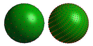
I needed a shape that was uniform from all angles. I researched and iterated through many different joint designs, including advanced dodecahedrons and custom ball designs, before deciding to use the math behind a Fibonacci sphere. A Fibonacci sphere is a mathematical model where a sphere has equidistant points on its surface, and by definition is THE model when it comes to getting the geometry I needed. While the shape isn't actually possible, we can approximate it using the Fibonacci sequence.
While the mathematical model itself has an abundance of online documentation, within the CAD community it is non-existent. I created my Fibonacci-inspired joint using a custom Python script within Fusion 360 that generated all the equidistant points and protrusion geometry.
Fibonacci Sphere Model

Cones generated via Python Script

Version 1
After finishing the model for my joint, I began creating the apparatus that could generate the string tension in two arms given easy-to-use user input. I decided to use a Sabertooth 2X12 motor controller with two 12V worm motors, along with an Arduino Nano commanding motor speed relative to the Analog value on two respective potentiometers.

Version 1 features
-
direct motor controlling using the mounted potentiometers
-
displayed motor speeds/output
-
cool see through visual display
-
metal mounting and PETG arm mounts


Bumps vs Cones

Version 1 Demo
Version 2
Version 2 changes and implementations
-
Integrated ACS712 current sensors for monitoring and preventing motor stalls
-
double OLED screen interface
-
Custom Soldered Break Out board with all screw terminal connections
-
Half-sized form factor and more accessible/robust design
-
120 lb strength internal cord


Future V2 additions
-
Flashlight and gripper arm heads
-
Vice system to secure the machine
-
Opening screen images